|
Photos of the prototype system
(click for details)

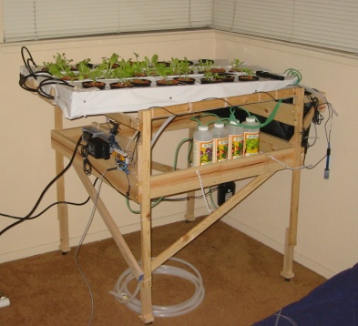
The nutrient dosing system,
including air pump
and mini-solenoid valves.

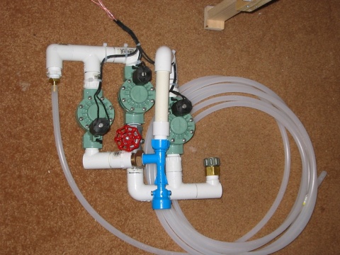
Fill and drain system

Prototype controller board

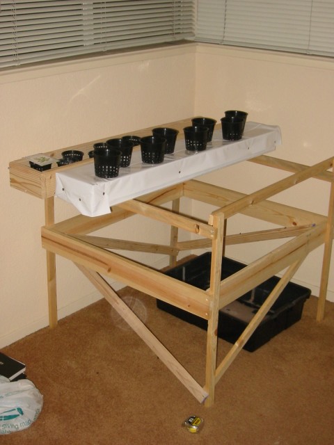
NFT channels under construction

After planting with lettuce and
herbs
|
Four operations are performed: fresh water fill, reservoir drain,
nutrient dosing, and AC power control. Also, parameters are
measured (such as temperature, pH, and electroconductivity.)
Since this is a prototype, the
hardware was constructed out of readily available materials. The
software is implemented mostly on a PC to allow for quick and easy
development. The final goal would be
to develop custom mechanical and electronic hardware, most likely
controlled by a midrange embedded microcontroller. For
developement and prototyping, a linux PC was chosen to help accelerate
algorithm development and testing.
Nutrient dosing
Standard hydro nutrients are contained their original 32 oz
bottles. A small aquarium air pump (3 psi max) is used to
pressurize the bottles. Four mini-solenoid valves dispense
accurate doses of individual nutrients. The intention is to use a
three-part nutrient formula and a pH control.
Fill and Drain System
The reservoir must be topped off with fresh water, as well as
drained periodically. I wanted to avoid using yet another pump
to do this, so I'm experimenting with a venturi vacuum device normally
used to fill and drain a waterbed using a regular faucet. Three
cheap ($10) lawn-sprinkler solenoid valves from are used to direct the
flow
either through the venturi or, after passing through a flow-restriction
valve, to the
reservoir. Turning on one valve fills the reservoir, turing on
two others
drains the reservoir. 3/4 inch PVC tubing is used to
connect everything, along with a 1/2 inch poly hose which runs to the
NFT bench.
Controller
A small controller board was designed to control AC power for three
outlets (for an HPS lamp, water pump, and the air pump), low voltage
DC for the fill/drain valves, and drivers for the mini-solenoids.
This board
also contains the analog circuitry for the sensors. Click
<here> for the circuit schematics. All communications
are via I2C serial bus. A very simple circuit converts a standard
PC parallel port into an I2C master. This is a bit longer
distance than I2C is normally used, but we are still within spec.
Hydroponic system
I'm using a newly constructed small indoor NFT system. Here I
wanted something cheap but functional. Commercial systems were
several-hundred dollars, but this wood frame, with poly-covered wooden
channels, was constructed on the cheap. (Home Depot saves the
day.) The small circulation pump, which is controlled by
software, will feed the tops of the NFT channels, with the return
flowing into the reservoir. (I will be using some of the
components of my outdoor system while it is down for the winter.)
The nutrient dispenser valves will overhang the reservoir edge.
The remote fill and drain system is connected to the reservoir and
controller via a long polyethylene hose, bound alongside two pairs of
copper wire.
The plants will get sunlight during the day, from two perpendicular
south-facing windows. Supplemental light may be
provided by an HPS lamp, also controlled by software.
Hardware / Software
The software to control the system is written in C and shell scripts
and is currently running under Linux. My system is a 400MHz Dell
laptop. All communication with the controller board is via I2C (a
low-speed serial interface @ 100kbps). A very simple I2C
interface board is connected to the parallel port. A bit-banging
linux I2C driver controls the lines, and all the software accesses the
bus in
userspace through the /dev/i2c-0 port. This makes it relatively
easy to read and write any device on the bus. The software is
basically a state machine with code to handle the various i2c devices.
The controller board consists of two 16-bit parallel I/O expanders
(MAX7311)
which drive all the relays and measure digital inputs like the float
switch, a 4 channel I2C analog to digital converter (MAX1138) to
measure the pH and
dispenser pressure, and a simple electroconductivity circuit, which
produces a variable
frequency output which varies with the nutrient concentration. A
binary ripple counter is used to count these pulses and it is read
periodically by software to determine the frequency of
oscillation. (A future enhancement would be to combine the ADC
and frequency counting functions on a single 8-pin PIC microcontroller
which implements an I2C slave.). An I2C temp sensor measures
ambient air temperature. Another sensor will measure reservoir
temp. The controller board provides 120VAC control for three
devices: HPS lamp (500W max), water pump, air pump. Four 12VDC
drivers control the nutrient solenoids. A spare Motorola
air-pressure sensor connects to the
airline tubing. Measuring the exact pressure in the bottles will
allow me to accurately guage the volume of nutrient dispensed.
(Since this sensor measures absolute pressure, it can also determine
the atmospheric barometric pressure when the pump is off and bottle
pressure has dissipated.)
The hardware is all hacked together on a protoboard, but I'm
considering spinning a PCB. I just need the time to do it.
Ideally
the board could fit into a slightly larger version of a standard power
strip. This form factor would make it convenient and
familiar. The
remote wires can connect to set of terminal blocks along one side.
|